To obtain the given truth table, the following logic gate should be placed at G:
Show Hint
For analyzing logic circuits:
- Start by identifying the effect of NOT, AND, and OR gates on the inputs.
- Derive the Boolean expression for the final output.
- Compare the derived expression with standard logic gate outputs to determine the correct gate.
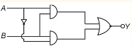
Step 1: Analyze the circuit structure.
- The given circuit consists of two NOT gates applied to \( A \) and \( B \), followed by two AND gates whose outputs feed into gate \( G \).
- The final truth table indicates that \( Y \) is high for \( (A, B) = (0,0) \) and \( (1,1) \), but low otherwise.
Step 2: Identify the logical expression.
Observing the output pattern, we recognize it corresponds to the NOR operation:
\[
Y = \overline{A + B}.
\]
Step 3: Select the appropriate gate.
- The only logic gate that produces \( Y = \overline{A + B} \) is the NOR Gate.
- Thus, the correct choice for gate \( G \) is a NOR gate.
Thus, the answer is \( \boxed{\text{NOR Gate}} \).
Was this answer helpful?
0
1
Show Solution
Verified By Collegedunia
Approach Solution -2
Step 1: Recall the behavior of the NOR gate.
A NOR gate gives output \(1\) only when all inputs are \(0\). Otherwise, the output is \(0\).
Step 2: Truth table for the NOR gate.
Input A
Input B
Output (A NOR B)
0
0
1
0
1
0
1
0
0
1
1
0
This matches the truth table given in the question — output is high (1) only when both inputs are low (0).


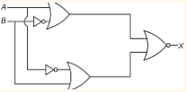 Draw truth table of given gate circuit.

 The output of the given circuit diagram is