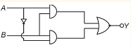
To identify the logic gate in the given circuit, let's analyze the image provided.
The circuit consists of two inputs, A and B, connected to an OR gate. The behavior of an OR gate is as follows:
If either input A or B is high (1), or both are high, the output Y is high (1).
If both inputs A and B are low (0), the output Y is low (0).
The logical operation performed by an OR gate can be described by the expression:
Y = A + B
Where '+' denotes the logical OR operation.
Now let's examine each option:
NAND gate: Outputs low only if both inputs are high. This does not match the circuit's behavior.
OR gate: Outputs high if at least one input is high, which matches the circuit's behavior.
AND gate: Outputs high only if both inputs are high. This does not match the circuit's behavior.
NOR gate: Outputs high only if both inputs are low. This does not match the circuit's behavior.
Considering the explanation above, the correct answer is indeed the OR gate.
Was this answer helpful?
0
0
Show Solution
Verified By Collegedunia
Approach Solution -2
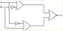
To identify the logic gate given in the circuit, we examine the components and connections depicted in the circuit diagram.
The circuit consists of two input lines, labeled A and B, each connected to an inverter (NOT gate). The output of each inverter is connected to the inputs of a third gate.
Each inverter (NOT gate) will output the opposite value of its input. Thus, if A = 0, the output of the inverter is 1, and if A = 1, the output is 0. This applies similarly to input B.
The two inverted outputs are fed into the main gate, which we need to identify.
If the main gate is an OR gate, it will output 1 if any of its inputs are 1. Since both inputs come from NOT gates, they will be high (1) if the original inputs were low (0), ensuring the OR gate outputs the correct result according to the truth table of an OR operation applied to inverted inputs.
This construction explains that the entire circuit acts as an OR gate when the two NOT gates (inverters) are present before it and the options provided. Therefore, the given circuit can be identified as an OR - gate.


 Draw truth table of given gate circuit.

 The output of the given circuit diagram is