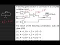
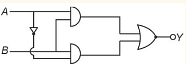
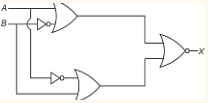
Following gates section is connected in a complete suitable circuit.

For which of the following combination, bulb will glow (ON):
For which of the following combination, bulb will glow (ON):
- A = 0, B = 1, C = 1, D = 1
- A = 1, B = 0, C = 0, D = 0
- A = 0, B = 0, C = 0, D = 1
- A = 1, B = 1, C = 1, D = 0
The Correct Option is B
Solution and Explanation
The bulb will glow if it experiences a potential drop across it. This requires one end of the bulb to be at a high state (1) and the other end to be at a low state (0).
In Option (2), setting \( A = 1, B = 0, C = 0, D = 0 \) satisfies this condition, as it results in the output of the OR gate being high, creating the required potential drop across the bulb.
Learn with videos:
Top JEE Main Physics Questions
- In a hydrogen like atom, when an electron jumps from the $M$ - shell to the $L$ - shell, the wavelength of emitted radiation is $\lambda$. If an electron jumps from $N$-shell to the $L$-shell, the wavelength of emitted radiation will be :
- Two masses $m$ and $\frac{m}{2}$ are connected at the two ends of a massless rigid rod of length $l$. The rod is suspended by a thin wire of torsional constant $k$ at the centre of mass of the rod-mass system(see figure). Because of torsional constant $k$, the restoring torque is $\tau =k\theta$ for angular displacement $\theta$. If the rod is rota ted by $\theta_0$ and released, the tension in it when it passes through its mean position will be:
A black body is at a temperature of 2880 K. The energy of radiation emitted by this body with wavelength between 499 nm and 500 nm is U1, between 999 nm and 1000 nm is U2 and between 1499 nm and 1500 nm is U3. The Wien's constant, b = 2.88×10⁶ nm-K. Then,
- $I _{ CM }$ is the moment of inertia of a circular disc about an axis (CM) passing through its center and perpendicular to the plane of disc $I_{A B}$ is it's moment of inertia about an axis $AB$ perpendicular to plane and parallel to axis $CM$ at a distance $\frac{2}{3} R$ from center Where $R$ is the radius of the dise The ratio of $I _{ AB }$ and $I _{ CM }$ is $x: 9$ The value of $x$ is______

- A nucleus disintegrates into two smaller parts, which have their velocities in the ratio $3: 2$ The ratio of their nuclear sizes will be $\left(\frac{x}{3}\right)^{\frac{1}{3}}$ The value of ' $x$ ' is:-
Top JEE Main Logic gates Questions
- The truth table for the combination of logical gates
 Draw truth table of given gate circuit.
- The truth table for this given circuit is :The truth table for this given circuit is :


In the truth table of the above circuit the value of X and Y are The output of the given circuit diagram is
Top JEE Main Questions
- In a hydrogen like atom, when an electron jumps from the $M$ - shell to the $L$ - shell, the wavelength of emitted radiation is $\lambda$. If an electron jumps from $N$-shell to the $L$-shell, the wavelength of emitted radiation will be :
- Two masses $m$ and $\frac{m}{2}$ are connected at the two ends of a massless rigid rod of length $l$. The rod is suspended by a thin wire of torsional constant $k$ at the centre of mass of the rod-mass system(see figure). Because of torsional constant $k$, the restoring torque is $\tau =k\theta$ for angular displacement $\theta$. If the rod is rota ted by $\theta_0$ and released, the tension in it when it passes through its mean position will be:
What will be the equilibrium constant of the given reaction carried out in a \(5 \,L\) vessel and having equilibrium amounts of \(A_2\) and \(A\) as \(0.5\) mole and \(2 \times 10^{-6}\) mole respectively?
The reaction : \(A_2 \rightleftharpoons 2A\)- The value of is
- The number of terms of an is even. The sum of the odd terms is and of the even terms is . The last term exceeds the first by . Then the number of terms in the series is ______.