Question:
In the circuit shown, \(V(t) = 2\sin(2000\pi t)\) Volts, where \(t\) is in seconds. The source \(V(t)\) drives the non-inverting (+) input of an opamp directly, the inverting (-) input is tied to ground (0 V), and the opamp is powered from +15 V and -15 V rails with no feedback network between its output and either input. Take the opamp to be ideal. Which of the following options is correct?
In the circuit shown, \(V(t) = 2\sin(2000\pi t)\) Volts, where \(t\) is in seconds. The source \(V(t)\) drives the non-inverting (+) input of an opamp directly, the inverting (-) input is tied to ground (0 V), and the opamp is powered from +15 V and -15 V rails with no feedback network between its output and either input. Take the opamp to be ideal. Which of the following options is correct?
Show Hint
With no feedback, an ideal opamp comparator output only ever sits at one of its two supply rails, comparing \(V(t)\) against the grounded inverting input tells you when it flips.
Updated On: Aug 17, 2026
- \(V_{out}(t)\) is square wave with peak-to-peak voltage = 30 V and time period is 1 ms.
- \(V_{out}(t)\) is a sine wave with peak-to-peak voltage = 4 V and time period is 1 ms.
- \(V_{out}(t)\) is sine wave with peak-to-peak voltage = 30 V and time period of 1 ms.
- \(V_{out}(t)\) is square wave with peak-to-peak voltage = 4 V and time period is 1 ms.
Show Solution

Verified By Collegedunia
The Correct Option is A
Solution and Explanation
Step 1: Understanding the Concept:
The opamp here has no feedback path from its output back to either input, so it is not being used as an amplifier, it is being used as an open-loop comparator. An ideal opamp with no feedback has effectively infinite gain, so the tiniest difference between its two inputs drives the output all the way to one power rail or the other.
Step 2: Key Formula or Approach:
Comparator rule: \(V_{out} = +V_{sat}\) when \(V_+ > V_-\), and \(V_{out} = -V_{sat}\) when \(V_+ < V_-\). Here \(V_+ = V(t)\) and \(V_- = 0\) (grounded), and the rails are \(\pm15\) V, so \(V_{sat}=15\) V.
Step 3: Detailed Explanation:
Since \(V_- = 0\), the comparison is simply whether \(V(t)\) is positive or negative.
When \(V(t) = 2\sin(2000\pi t) > 0\), the output snaps to \(+15\) V.
When \(V(t) < 0\), the output snaps to \(-15\) V.
This makes \(V_{out}(t)\) a square wave (not a scaled copy of the sine wave) that flips sign exactly when \(V(t)\) crosses zero.
Peak-to-peak amplitude: \[ V_{pp} = 15 - (-15) = 30\ \text{V} \]
Time period: \(V(t)\) has angular frequency \(\omega = 2000\pi\) rad/s, and the output switches at the same zero crossings as \(V(t)\), so it repeats with the same period as \(V(t)\): \[ T = \frac{2\pi}{\omega} = \frac{2\pi}{2000\pi} = \frac{1}{1000}\ \text{s} = 1\ \text{ms} \]
Step 4: Why the other options are wrong.
Options (B) and (C) both say the output is a sine wave. An open-loop opamp with no feedback cannot produce a sine wave, its output can only sit at one of the two rails, so it must be a square wave.
Option (D) has the right waveform shape but the wrong amplitude, 4 V is nowhere close to the rail-to-rail swing of 30 V that an ideal saturated opamp actually produces.
Final Answer:
The comparator output is a 30 V peak-to-peak square wave with a 1 ms period. \[ \boxed{V_{pp} = 30\ \text{V},\ T = 1\ \text{ms}} \]
The opamp here has no feedback path from its output back to either input, so it is not being used as an amplifier, it is being used as an open-loop comparator. An ideal opamp with no feedback has effectively infinite gain, so the tiniest difference between its two inputs drives the output all the way to one power rail or the other.
Step 2: Key Formula or Approach:
Comparator rule: \(V_{out} = +V_{sat}\) when \(V_+ > V_-\), and \(V_{out} = -V_{sat}\) when \(V_+ < V_-\). Here \(V_+ = V(t)\) and \(V_- = 0\) (grounded), and the rails are \(\pm15\) V, so \(V_{sat}=15\) V.
Step 3: Detailed Explanation:
Since \(V_- = 0\), the comparison is simply whether \(V(t)\) is positive or negative.
When \(V(t) = 2\sin(2000\pi t) > 0\), the output snaps to \(+15\) V.
When \(V(t) < 0\), the output snaps to \(-15\) V.
This makes \(V_{out}(t)\) a square wave (not a scaled copy of the sine wave) that flips sign exactly when \(V(t)\) crosses zero.
Peak-to-peak amplitude: \[ V_{pp} = 15 - (-15) = 30\ \text{V} \]
Time period: \(V(t)\) has angular frequency \(\omega = 2000\pi\) rad/s, and the output switches at the same zero crossings as \(V(t)\), so it repeats with the same period as \(V(t)\): \[ T = \frac{2\pi}{\omega} = \frac{2\pi}{2000\pi} = \frac{1}{1000}\ \text{s} = 1\ \text{ms} \]
Step 4: Why the other options are wrong.
Options (B) and (C) both say the output is a sine wave. An open-loop opamp with no feedback cannot produce a sine wave, its output can only sit at one of the two rails, so it must be a square wave.
Option (D) has the right waveform shape but the wrong amplitude, 4 V is nowhere close to the rail-to-rail swing of 30 V that an ideal saturated opamp actually produces.
Final Answer:
The comparator output is a 30 V peak-to-peak square wave with a 1 ms period. \[ \boxed{V_{pp} = 30\ \text{V},\ T = 1\ \text{ms}} \]
Was this answer helpful?
0
0
Top GATE PH Physics Questions
- An infinite one-dimensional lattice extends along the x-axis. At each lattice site, there exists an ion with spin 1/2. The spin can point either in the +z or -z direction only. Let \( S_P \), \( S_F \), and \( S_A \) denote the entropies of paramagnetic, ferromagnetic, and antiferromagnetic configurations, respectively. Which of the following relations is/are true?
- Two point charges of charge \( +q \) each are placed a distance \( 2d \) apart. A grounded solid conducting sphere of radius \( a \) is placed midway between them. Assume \( a^2 \ll d^2 \). Which of the following statements is/are true?
- A particle of mass $m$ is moving in the potential
\[ V(x) = \begin{cases} V_0 + \frac{1}{2} m \omega_{0P}^2 x^2 & \quad \text{if } x > 0 \\ \infty & \quad \text{if } x \leq 0 \end{cases} \]
Figures P, Q, R, and S show different combinations of the values of $ \omega_0 $ and $ V_0 $. - Decays of mesons and baryons can be categorized as weak, strong and electromagnetic decays depending upon the interactions involved in the processes. Which of the following option is/are true?
- The temperature \( T \) dependence of magnetic susceptibility \( \chi \) (Column I) of certain magnetic materials (Column II) are given below. Which of the following options is/are correct?
Column I Column II (1) 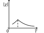
(P) Diamagnetic (2) 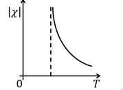
(Q) Paramagnetic (3) 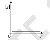
(R) Ferromagnetic (4) 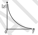
(S) Antiferromagnetic
View More Questions
Top GATE PH Electronics Questions

Top GATE PH Questions
- If \( F_1(Q, q) = Qq \) is the generating function of a canonical transformation from \((p, q)\) to \((P, Q)\), then which one of the following relations is correct?
- When an unpolarized plane electromagnetic wave in a dielectric medium with refractive index \( n_1 \) is incident on a plane interface separating it from another dielectric medium with refractive index \( n_2 \) (where \( n_2 > n_1 \)), and the angle of incidence is \(\tan^{-1} \left( \frac{n_2}{n_1} \right) \), the following statement is true:
- The wavefunction of a particle in an infinite one-dimensional potential well at time \( t \) is
\[ \Psi(x, t) = \sqrt{\frac{2}{3}} e^{-iE_1 t/\hbar}\psi_1(x) + \frac{1}{\sqrt{6}} e^{i\pi/6} e^{-iE_2 t/\hbar} \psi_2(x) + \frac{1}{\sqrt{6}} e^{i\pi/4} e^{-iE_3 t/\hbar} \psi_3(x) \]where \(\psi_1\), \(\psi_2\), and \(\psi_3\) are the normalized ground state, the normalized first excited state, and the normalized second excited state, respectively. \(E_1\), \(E_2\), and \(E_3\) are the eigen-energies corresponding to \(\psi_1\), \(\psi_2\), and \(\psi_3\), respectively. The expectation value of energy of the particle in state \(\Psi(x,t)\) is - If a thermodynamical system is adiabatically isolated and experiences a change in volume under an externally applied constant pressure, then the thermodynamical potential minimized at equilibrium is the
- The mean distance between the two atoms of an HD molecule is \( r \), where H and D denote hydrogen and deuterium, respectively. The mass of the hydrogen atom is \( m_H \). The energy difference between the two lowest lying rotational states of HD in multiples of \(\frac{h^2}{m_H r^2}\) is:
View More Questions