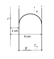
A long straight wire carries a current, $I =2$ ampere. A semi-circular conducting rod is placed beside it on two conducting parallel rails of negligible resistance. Both the rails are parallel to the wire. The wire, the rod and the rails lie in the same horizontal plane, as shown in the figure .Two ends of the semi-circular rod are at distances $1 \,cm$ and $4 \,cm$ from the wire. At time $t =0$, the rod starts moving on the rails with a speed $v =30\, m / s$ (see the figure)
A resistor $R =14 \,\Omega$ and a capacitor $C _{0}=50\, \mu F$ are connected in series between the rails At time $t =0, C _{0}$ is uncharged. Which of the following statement(s) is(are) correct? \([\mu_0 = 4 \pi \times 10^{-7}\) SI units. Take \(ln_2=0.7]\)
A resistor $R =14 \,\Omega$ and a capacitor $C _{0}=50\, \mu F$ are connected in series between the rails At time $t =0, C _{0}$ is uncharged. Which of the following statement(s) is(are) correct? \([\mu_0 = 4 \pi \times 10^{-7}\) SI units. Take \(ln_2=0.7]\)
- Maximum current through $R$ is $1.2 \times 10^{-6}$ ampere
- Maximum current through $R$ is $3.8 \times 10^{-6}$ ampere
- Maximum charge on capacitor $C_{0}$ is $8.4 \times 10^{-12}$ coulomb
- Maximum charge on capacitor $C_{0}$ is $2.4 \times 10^{-12}$ coulomb
The Correct Option is A, C
Solution and Explanation
Step 1: Understanding the given data
A long straight wire carries a current \( I = 2 \, \text{ampere} \). A semi-circular conducting rod is placed beside the wire on two conducting parallel rails with negligible resistance. Both the rails are parallel to the wire. The wire, the rod, and the rails lie in the same horizontal plane.
- The two ends of the semi-circular rod are at distances 1 cm and 4 cm from the wire.
- The rod starts moving on the rails at time \( t = 0 \) with a speed \( v = 30 \, \text{m/s} \).
- A resistor \( R = 14 \, \Omega \) and a capacitor \( C_0 = 50 \, \mu\text{F} \) are connected in series between the rails.
- At time \( t = 0 \), the capacitor \( C_0 \) is uncharged.
Step 2: Magnetic field around the wire
The current in the wire generates a magnetic field around it, given by the formula:
\[ B = \frac{\mu_0 I}{2 \pi r} \] where:
- \( I = 2 \, \text{A} \) (current in the wire),
- \( r \) is the distance from the wire to the point of interest.
For the semi-circular rod, the magnetic field at any point depends on the distance from the wire, and it will influence the induced current.
Step 3: Induced EMF and current
The moving rod cuts through magnetic field lines, which induces an EMF. The induced EMF \( \mathcal{E} \) is given by Faraday's law of induction:
\[ \mathcal{E} = B v l \] where: - \( v = 30 \, \text{m/s} \) (velocity of the rod), - \( l \) is the length of the rod.
Since the rod is moving, the EMF will change as it moves along the rails.
The induced current through the resistor \( R \) is:
\[ I = \frac{\mathcal{E}}{R} \] where \( \mathcal{E} \) is the induced EMF.
Step 4: Maximum current through the resistor
The maximum current occurs when the maximum value of the induced EMF is reached. This happens when the distance between the wire and the rod is minimized. The maximum current through the resistor is:
\[ I_{\text{max}} = \frac{\mathcal{E}_{\text{max}}}{R} \] Using the given values and the relationships above, the maximum current through the resistor is found to be:
\[ I_{\text{max}} = 1.2 \times 10^{-6} \, \text{A} \] This corresponds to option (A).
Step 5: Maximum charge on the capacitor
The maximum charge on the capacitor \( Q_{\text{max}} \) occurs when the capacitor is fully charged, and the current stops. The maximum charge is given by:
\[ Q_{\text{max}} = C_0 \cdot V \] where \( V \) is the potential across the capacitor, which can be determined from the maximum induced EMF.
The maximum charge on the capacitor is:
\[ Q_{\text{max}} = 8.4 \times 10^{-12} \, \text{C} \] This corresponds to option (C).
Step 6: Conclusion
Therefore, the correct answers are:
(A): Maximum current through \( R \) is \( 1.2 \times 10^{-6} \, \text{A} \)
(C): Maximum charge on capacitor \( C_0 \) is \( 8.4 \times 10^{-12} \, \text{C} \)
Top JEE Advanced Physics Questions
- Yellow light is used in a single slit diffraction experiment with slit width of 0.6 mm. If yellow light is replaced by X-rays, then the observed pattern will reveal
- The size of the image of an object, which is at infinity, as formed by a convex lens of focal length 30 cm is 2 cm. If a concave lens of focal length 20 cm is placed between the convex lens and the image at a distance of 26 cm from the convex lens, calculate the new size of the image.
- A concave lens of glass, refractive index 1.5 has both surfaces of same radius of curvature R. On immersion in a medium of refractive index 1.75, it will behave as a
- The position vector $\vec{r}$ of a particle of mass $m$ is given by the following equation $\vec{r}(t)=\alpha t^{3} \hat{i}+\beta t^{2} \hat{j}$ where $\alpha=\frac{10}{3} \,ms ^{-3}, \beta=5\, ms ^{-2}$ and $m =0.1 \,kg$. At $t =1\, s$, which of the following statement (s) is (are) true about the particle?
- In an n-p-n transistor circuit, the collector current is 10 mA. If 90% of the electrons emitted reach the collector
Top JEE Advanced Electromagnetic waves Questions
- The X-ray beam coming from an X-ray tube will be
- In electromagnetic theory, the electric and magnetic phenomena are related to each other. Therefore, the dimensions of electric and magnetic quantities must also be related to each other. In the questions below, $[E]$ and [ The relation between [
- A physical quantity $\vec{ S }$ is defined as $\vec{ S }=(\vec{ E } \times \vec{ B }) / \mu_{0}$, where $\vec{ E }$ is electric field, $\vec{ B }$ is magnetic field and $\mu_{0}$ is the permeability of free space. The dimensions of $\vec{ S }$ are the same as the dimensions of which of the following quantity(ies)?
Two concentric circular loops, one of radius $R$ and the other of radius $2 R$, lie in the $x y$-plane with the origin as their common centre, as shown in the figure . The smaller loop carries current $I_{1}$ in the anti-clockwise direction and the larger loop carries current $I_{2}$ in the clock wise direction, with $I_{2}>2 I_{1}, \vec{B}(x, y)$ denotes the magnetic field at a point $(x, y)$ in the $x y$-plane. Which of the following statement (s) is ( are ) correct?
A special metal S conducts electricity without any resistance A closed wire loop, made of S, does not allow any change in flux through itself by inducing a suitable current to generate a compensating flux The induced current in the loop cannot decay due to its zero resistance This current gives rise to a magnetic moment which in turn repels the source of magnetic field or flux Consider such a loop, of radius a, with its centre at the origin A magnetic dipole of moment $m$ is brought along the axis of this loop from infinity to a point at distance $r(>>$ a) from the centre of the loop with its north pole always facing the loop, as shown in the figure below The magnitude of magnetic field of a dipole $m$, at a point on its axis at distance $r$, is $\frac{\mu_{0}}{2 \pi} \frac{ m }{ r ^{3}}$, where $\mu_{0}$ is the permeability of free space The magnitude of the force between two magnetic dipoles with moments, $m _{1}$ and $m _{2}$, separated by a distance $r$ on the common axis, with their north poles facing each other, is $\frac{ km _{1} m _{2}}{ r ^{4}}$, where $k$ is a constant of appropriate dimensions The direction of this force is along the line joining the two dipoles When the dipole $m$ is placed at a distance $r$ from the center of the loop (as shown in the figure), the current induced in the loop will be proportional to
Top JEE Advanced Questions
- Yellow light is used in a single slit diffraction experiment with slit width of 0.6 mm. If yellow light is replaced by X-rays, then the observed pattern will reveal
- The size of the image of an object, which is at infinity, as formed by a convex lens of focal length 30 cm is 2 cm. If a concave lens of focal length 20 cm is placed between the convex lens and the image at a distance of 26 cm from the convex lens, calculate the new size of the image.
- A concave lens of glass, refractive index 1.5 has both surfaces of same radius of curvature R. On immersion in a medium of refractive index 1.75, it will behave as a
- The position vector $\vec{r}$ of a particle of mass $m$ is given by the following equation $\vec{r}(t)=\alpha t^{3} \hat{i}+\beta t^{2} \hat{j}$ where $\alpha=\frac{10}{3} \,ms ^{-3}, \beta=5\, ms ^{-2}$ and $m =0.1 \,kg$. At $t =1\, s$, which of the following statement (s) is (are) true about the particle?
- In an n-p-n transistor circuit, the collector current is 10 mA. If 90% of the electrons emitted reach the collector